Infrared (IR) technology is widely used in remote controls, automation systems, and communication devices. The Arduino Pro Micro, a compact and powerful microcontroller, provides an excellent platform for working with IR LEDs. This guide will walk you through how to connect IR LED to Arduino Pro Micro, wiring it properly, and programming it to send IR signals. By the end of this guide, you’ll have a fully functional IR LED setup capable of transmitting signals to control devices such as TVs, air conditioners, or custom automation projects.
Understanding the IR LED and Arduino Pro Micro
What is an IR LED?
An Infrared Light Emitting Diode (IR LED) is a type of LED that emits infrared light, which is invisible to the human eye. It is commonly used in:
- Remote controls
- Proximity sensors
- Data transmission
IR LEDs operate at wavelengths between 850nm to 950nm and require a specific modulation frequency (often 38kHz) to communicate with IR receivers.
Why Use Arduino Pro Micro?
The Arduino Pro Micro is a compact, ATmega32U4-based microcontroller that is ideal for projects requiring small form factors. It features:
- 5V operation (same voltage needed for IR LEDs)
- Built-in USB for easy programming
- Compact design for embedded applications
Since the Pro Micro is powerful yet small, it’s perfect for IR-based control systems and IoT projects.
Components Required
To build this project, you need the following components:
| Component | Quantity |
|---|---|
| Arduino Pro Micro | 1 |
| IR LED (950nm, 38kHz) | 1 |
| 220Ω Resistor | 1 |
| Breadboard | 1 |
| Jumper Wires | As needed |
| TSOP IR Receiver (optional) | 1 |
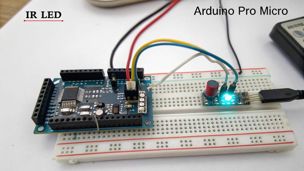
Wiring Diagram
To connect the IR LED to the Arduino Pro Micro, follow these steps:
- Connect the longer leg (Anode) of the IR LED to pin 9 of the Arduino through a 220Ω resistor.
- Connect the shorter leg (Cathode) of the IR LED to GND (Ground).
- Optional: If you are using an IR Receiver, connect:
- VCC of the Receiver to 5V of Arduino
- GND of the Receiver to GND
- Signal pin of the Receiver to pin 2 of the Arduino
Here’s the circuit diagram:
     +5V  o---(Optional TSOP)---o VCC
            |
        IR LED
            |
     Pin 9  o------[220Ω]------|>|-----o GND
Programming the Arduino Pro Micro
To control the IR LED, we need to generate 38kHz modulated signals. The IRremote library simplifies this process.
Installing the IRremote Library
- Open Arduino IDE.
- Go to Sketch → Include Library → Manage Libraries.
- Search for IRremote by Arduino-IRremote.
- Click Install.
Sending IR Signals with the IR LED
Upload the following code to send a Power ON signal to a TV (Sony protocol).
#include <IRremote.h>

#define IR_LED_PIN 9  // The IR LED is connected to pin 9

IRsend irsend;  // Create an instance of IRsend

void setup() {
    pinMode(IR_LED_PIN, OUTPUT);
}

void loop() {
    irsend.sendSony(0xa90, 12);  // Sony Power ON code (0xA90)
    delay(2000); // Send signal every 2 seconds
}
Explanation of the Code
- IRsend irsend; → Creates an IR sender instance.
- sendSony(0xa90, 12); → Sends a Sony Power ON signal.
- delay(2000); → Sends the signal every 2 seconds.
Testing the IR LED Setup
Checking the IR LED Output
Since IR light is invisible to the human eye, use a smartphone camera to see if it’s working:
- Open the camera app on your phone.
- Point the IR LED at the camera.
- If working, you should see a blinking light on the screen.
Testing with an IR Receiver
If you have an IR Receiver, upload this test code to check if the IR LED is transmitting:
#include <IRremote.h>

#define RECV_PIN 2  // IR Receiver connected to Pin 2

IRrecv irrecv(RECV_PIN);
decode_results results;

void setup() {
    Serial.begin(9600);
    irrecv.enableIRIn();  // Start the receiver
}

void loop() {
    if (irrecv.decode(&results)) {
        Serial.println(results.value, HEX);  // Print received signal
        irrecv.resume();  // Receive the next signal
    }
}
- Open the Serial Monitor (
9600 baud). - Press the remote control button or run the IR LED test code.
- If the LED is working, you will see hex codes printed in the serial monitor.
Applications of IR LED with Arduino Pro Micro
Here are some exciting projects you can build with IR LEDs and Arduino Pro Micro:
1. Universal TV Remote
- Store multiple IR codes to control TV, AC, and music systems.
2. IR-based Home Automation
- Control lights, fans, or appliances with IR signals.
3. Infrared Data Transmission
- Send data between two Arduinos using IR LED and IR Receiver.
4. Gesture-based Control
- Use IR sensors for gesture recognition.
Common Troubleshooting Issues
IR LED Not Blinking
- Ensure correct polarity of the LED.
- Use a 220Ω resistor, not a higher value.
- Check wiring connections.
IR Signal Not Recognized
- Verify the IR remote code format.
- Ensure 38kHz modulation.
No Output in Serial Monitor
- Confirm the receiver is connected to pin 2.
- Check power supply to the receiver.
Also Choose the Right Smartphone for Your Business.
FAQs
How do I know if my IR LED is working?
Use a smartphone camera to see the IR LED blinking.
Which pin should I connect my IR LED to on Arduino Pro Micro?
Use pin 9, as it supports PWM modulation.
Can I use an IR LED for two-way communication?
Yes, but you need an IR receiver to decode incoming signals.
What is the range of an IR LED?
Typical range is 5-10 meters, depending on power and obstacles.
Can I use multiple IR LEDs with Arduino?
Yes, but each requires a separate resistor and PWM-capable pin.
Conclusion
Connecting an IR LED to an Arduino Pro Micro opens up a range of possibilities for remote control and automation projects. By following this guide, you now have a working IR transmission system that can be expanded into smart home applications, robotic control, and more.
Keep experimenting and have fun with Arduino and IR communication!